Showing posts with label IOT. Show all posts

Saturday, 9 April 2022

IOT: First Steps for the Robot Project

One important part of my IOT project will be to have a small robot that can move around in my house and stream video/pictures with an acceptable delay.

I spotted a platform/robot car that I can start with at a Swedish electronics store and I've spent a couple of evenings with my four year old son building the basic design. In the original setup, the robot uses an ultrasound sensor to determine in what direction it will move.

The robot car consists of:

  • An Arduino board (a very limited computer)
  • A H bridge that controls the engines
  • A pair of simple analog engines that takes 5-10 volts as input.
  • An ultra sound sensor
  • A servo motor that moves the sensor in different directions.
  • A battery pack of 6 AA/LR6 batteries that gives 9 volts.

I've disconnected the original battery pack and replaced it with a power bank.
Later, I've removed the battery pack.


Connecting a Raspberry PI Computer.

The original setup feeds 9 volts both to the engines and to the Arduino board via the DC jack. However, I want to use a Raspberry PI computer with a camera module. 

With the Raspberry PI computer, I can connect to the internet over Wi-Fi, setup a video stream or a web server and do some imaging. An USB/Serial connection can handle the interface between the Arduino and the Raspberry PI.

However, it is not that straightforward to connect a Raspberry PI to the Arduino in this setup. The manufacturer recommends that the battery pack is disconnected before connecting to the USB port on the Arduino. There are two options to communicate between the Arduino and another computer:

  1. Keep the batteries and connect a cable to GPIO pins on the Arduino and Raspberry PI. Since the boards are operating on different voltages (5 V and 3.3 V respectively), I would need a level shifter in between.
  2. Remove the battery pack and connect the Arduino to the Raspberry PI. That would mean that the motors will get only 5 V. This is the easiest solution, I'll maybe explore the other solution later. Another advantage is that I'll reduce the weight of the vehicle.

I've replaced the battery pack with a LEGO rig for the Raspberry PI computer. 

In the next blog post, I'll modify the code of the Arduino so that I can send commands to it via the Raspberry PI.

Saturday, 11 September 2021

IOT: Designing the Arduino Part of the Face Recognition System

After finalizing the Stock Analyzer project, installing Solar Panels to my house and exploring Quantum Computers, I will continue with my IOT project. 

I am currently able to detect a face using OpenCV on a laptop. The next step will be to migrate that functionality to a headless Raspberry PI that is connected to an Arduino. In this blog post, I will design the Arduino board.

The person in the picture is more similar to James Dean than to Marlon Brando and Audrey Hepburn.
 Training data is very limited, with only 20 pictures of three celebrities, and that causes the identifier to perform poorly
. 

The Arduino Panel
When a user is pressing a button on Arduino, the RPI will take pictures every x seconds. It will try to identify the faces on the last picture. If a face is identified, it will send the corresponding name back to the Arduino. The names will show on the LCD and corresponding LED's will activate. If faces are detected but not identified, an alarm will activate. 

The Piezo element and the red LED to the left are used for alarms.
The button sends a start/stop signal to the connected Raspberry PI computer.
The four LEDs to the right identifies four persons. 


There are three cases:
  • No face is detected on the last picture
  • At least one familiar faces - disable the alarm, if active.
  • No familiar faces - start an alarm.


Saturday, 13 March 2021

IOT: Data from computer to Arduino

One of the tasks on my first IOT  project anatomy is to send data to the Arduino from Raspberry PI to my Arduino board. 

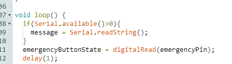
There is one Arduino feature one needs to consider when sending serial data to Arduino over USB port: Every the serial connection is established, the Arduino is reset. This is a feature that simplifies the process of loading software to the board. 

If a script establishes a serial connection to the Arduino, it takes one second for the board to boot. If the script sends serial data during that time, that data is lost. Further, if the connection is released and reestablished, the board reboots.

My solution to that issue is to wait for the board to boot and to keep the connection alive during the entire session.

The data must be encoded to binary format

The sender script specifies interface, baudrate and timeout and the receiving script sends the incoming string to the display for some seconds. 

And finally, the incoming message is shown on the Arduino LCD.

I'm getting close to completion of the first step of my IOT journey. The remaining tasks are to make the Raspberry Pi available from the external internet, send SMS from the router and to push pictures to the cloud from the Raspberry Pi whenever someone activates the emergency button.

After that, I'll plan the next steps for the IOT project.


Saturday, 6 March 2021

IOT: Connecting Raspberry Pi to Thingspeak

This one was easier than I thought. I wanted to send/log data from my Raspberry Pi to Thingspeak. 

Step 1 - Activate a Thingspeak Account and set up a channel

The channel has a number of fields. In this case, I use only one field, "field1".

Step 2 - Get an API key for Thingspeak

The API Write key is necessary for Thingspeak to know what channel to publish to. 


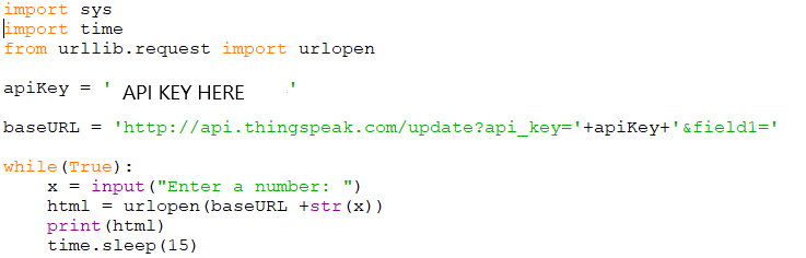
Step 3 - Send data to Thingspeak using "POST" with the channel number and the data.
The free version of Thingspeak allows for one update every 15 seconds. My script simply takes a number from the console and posts it to Thingspeak with a 15 second interval.


The result:

Saturday, 20 February 2021

RPI: Streaming Video from Internal Website

Previously, I was able to setup a web camera with an update interval of 5 seconds. Now, I want to stream video from the camera.

Option 1: Using a Script to Implement a Super Simple Web Server with Webcam:

I followed the tutorial and got a pretty good result. There is some lag in the video stream, but overall the experience is quite good.

The Python script implements:

  • a small web server, which can make it hard to embed into a larger web site. 
  • a stream using the camera that is fed to the web site.

In this case, the web server and stream are on port 8000. 

The drawback with this approach is that the web server is extremely simple and hard to integrate to other functionality. The other option is even simpler: Using YouTube to stream the video.

Option 2: Stream Video Over YouTube

Step 1 - Preparations

First, I need to activate live streaming online on Youtube: 

"Sänd live" translates to "Go live".


There is a 24 hour delay to activate the "Go Live" functionality. For the mobile app, it seems that the "Go Live" feature is only available to accounts with more than 1000 viewers. I plan to stream from RPI using an encoder, so I hope that it will work anyways.

I expect streaming from a RPI to generate quite some heat, so I have removed the Lego case for my RPI as a precaution. 

Step 2 - Setting Up Livestream and saving URL and key

Step 3 - Running ffmpg / raspivid command from RPI

I use this command:

raspivid -o - -t 0 -vf -hf -fps 30 -b 6000000 | ffmpeg -re -ar 44100 -ac 2 -acodec pcm_s16le -f s16le -ac 2 -i /dev/zero -f h264 -i - -vcodec copy -acodec aac -ab 128k -g 50 -strict experimental -f flv rtmp://a.rtmp.youtube.com/live2/<SESSION>

raspivid captures video from a Raspberry Pi Camera module. The different options are:

  • -o - means that the output will be sent to stdout. Actually, it will be piped to ffmpeg. 
  • -vf  and -hf  means that the stream will be vertically flipped.
  • -fps 30 means that the stream will capture 30 frames per second
  • -b 6000000 means that the bit rate will be 6Mbit per second. It is maybe too much for the built in wifi adapter, so I may have to reduce the bitrate. 

The output is piped to ffmpeg that is used to record, convert and stream video. 

  • -re means reading input at native frame rate.
  • -ar 44100 sets the audio sampling frequency. The Raspberry Pi Camera module doesn't support audio so I should be able to skip this one.
  • -ac 2 sets the number of audio channels to two. I should be able to skip this one too.
  • -acodec pcm_s16le sets the audio codec.  I should be able to skip this one too.
  •  -f s16le forces format, like signed, 16 bits and little endian. 
  •  -i /dev/zero specifies input filename. This input provides a continuous stream of null characters. I don't know why that is specified to be the input.
  • -f h264 forces the format to H.264, a video coding format used in mpeg-4 
  • -vcodec copy means that the raw codec data is copied as is.
  •  -acodec aac -specifies audio codec againg
  • -ab 128k -sets the audio bitrate.
  • -g 50 sets the "Group of Pictures" size to 50
  • -strict experimental - specifies that the program doesn't need to be super-strict to the standards
  • -f flv rtmp://a.rtmp.youtube.com/live2/<SESSION> forces the output to go to my Youtube stream

The streaming key must be copied to the RPI CLI command.

I had ffmpeg installed already, so I didn't need to recompile it. The first streaming attempt had the image flipped upside down. After removing the fv and hv flags, the stream was initiated properly. 

It took a short while before the stream appeared on my Youtube channel.

This makes it much easier to access streams from my RPI. As long as I have the link to the stream, I can access it. I'll also be able to embed the stream into a html page.


Saturday, 30 January 2021

IOT: Data from Arduino to Raspberry PI

In this step, I'll send data from Arduino to Raspberry PI. 

When the user activates the emergency function, a signal will be sent to the RPI that will take a photo and publish on a web server. You can find more information about the traffic lights project here.

Step 1: Connecting Arduino to Raspberry PI

The RPI is connected to a camera module.
A USB cable connects power and serial from the RPI to the Arduino.


The first step is to find the serial port. For the RPI, I've compared the tty ports without and with the Arduino.

The interface /dev/ttyACM0 shows up when I connect the Arduino over USB.

I uploaded a small python script with code that I found on DiyIOt from my Windows computer to my Raspberry PI.

I added a couple of lines to take a photo on the webcam


Step 2: Take a picture, if the emergency button is pressed.
The script checks if the message matches the expected string. If it does, the script will ask the shell to take a photo and save it in /var/www/html/ folder.

When the RPI detects "Switch to Emergency", it captures a JPEG image.
In order to reduce the download time, I've selected a lower resolution than the 3280x2464 that is supported.

Step 3: Publish the image on the web server
The /var/www/html folder is owned by root. This makes it hard to save files there automatically. To resolve this, I've changed the ownership and permissions for that folder. 

A very simple web page that reloads every third second shows the picture. Code and screenshot below:

The updated webpage looks like this:

Now, an event on the Arduino can trigger the RPI to take a photo and show it on an internal web page. The next step will be to send some feedback from RPI to Arduino and to explore video streaming from RPI.


Saturday, 2 January 2021

2020 in Retrospect

2020 was a dramatic year for me and that had some impact on my pet projects. 

The first wave of the pandemic came when I and my family moved to our current home in Åkarp. Luckily, that didn't affect the relocation and the contractors we used for fixing things in the house.

We got our second son when the second wave was escalating in December. 

The pet projects still had some progress:

StockPredictor (C#, Python, SQL and Machine Learning): I created a Python script that connected to the SQL database and analyzed the data, for example identifying stock splits. I also made some improvements to the web scraper. After several months of work with the data, I was able to apply some machine learning algorithms to the data. As expected, the MLPRegressor wasn't able to predict future stock values - it seems that the market is quite efficient.

IOT (Arduino, Raspberry PI): I explored Arduino and followed some simple experiments to learn the basic concepts. After that, I created a simple set of traffic lights with an emergency button and a LCD display. For Raspberry PI, I brought up the system.

In 2021, I'll mainly focus on the house, work and family.  I still think I can have some progress on my pet project in IOT.

Saturday, 5 December 2020

IOT: Setting Up a Web Camera for a Headless Raspberry PI

In my IOT project, I need to take pictures with a headless Raspberry PI. 

The camera that I use today is an  USB 8$ web camera with a picture resolution of 640x480. It is a temporary solution - the official camera module v2 supports a resolution of 3280x2464 pixels and weighs only 3g.

In this project, I followed the documentation.

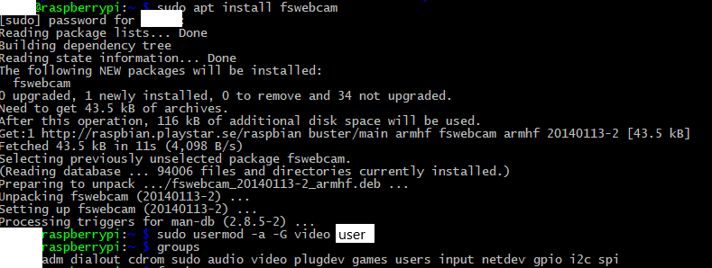
After connecting it to a USB port, I installed the fswebcam package:

Using the camera from command line is easy. If the resolution flag isn't specified, the RPI will use a lower resolution: 

The resulting picture has a time stamp in the lower part.

Sometimes, I need to get the pictures to my Windows 10 computer. Since I'm familiar with the scp command, I needed to install it in Microsoft PowerShell:

So far, it is quite straight forward to use Raspberry PI. The earlier models were launched eight years ago, so many of the early bugs and features has been solved over the last years. My board, Raspberry PI 3 B+ was launched three years ago.

The next step will be to setup a web server with a Wordpress web page on the Raspberry PI. I will use that for posting pictures from the web camera. Or maybe I'll just use a Python script for posting the picture on a dedicated blog.


Saturday, 14 November 2020

IOT: Traffic Lights with Arduino

My first IOT project will be a pair of traffic lights that are simulating an intersection.

Iteration 1 - Time Controlled Traffic Lights: 

I've connected six LED's to the outputs of the Arduino Uno. A simple C++ program controls it. The program toggles between the two sets of traffic lights in a sequence that is common in Europe. 

Design and the code that I wrote. I used TinkerCad for making the drawing.

The code and the latest version of the sketch is available on my TinkerCad page.

Step 2 - Emergency Button

The next step is to add an "Emergency Button". Whenever someone presses that button, both sets of traffic lights switches to red and wait until the user presses the button again. Further, the RGB led will blink during that time.   


I only use two input pins for the RGB LED, since that will blink in red or blue only.
I control the brightness of that LED with Pulse Width Modulation.

When the user pushes the button (button state changes to HIGH), the system will either enter or leave the emergency state.

I had some issues with the board leaving the emergency state. The fault was mine - I messed up the output numbers and I sent output to input ports.

The next step will be more complex - I'll add a 16x2 LCD display to the system that will print some useful information to the user.

Saturday, 7 November 2020

IOT: Getting Used with Arduino

 To learn Arduino, I've bought the Arduino Starter Kit. It contains an Arduino board, together with components needed for basic projects and a book that describes the projects. 

The first steps for me is to simply follow the examples in the book. I won't discuss this in detail in the blog, unless I do interesting findings.

Setting Up the Integrated Development Environment

Instead of downloading an Integrated Development Environment for Arduino, I decided to go for the web based option. The compilation of the code is done in the cloud (AWS). A small plugin (Arduino Create) is still needed on my laptop to handle the communication to the board.

Following the Book

From an engineering point of view, this isn't that interesting - but it was an important step. I needed to get my hands dirty and learn how to read the markings on the resistors, understand the difference between the long and short leg of diodes and understand why defensive programming is a good thing.


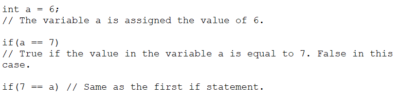
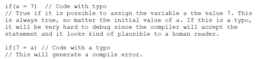
It is easy to make the first typo.
I did it, and I spent quite a while finding that bug.
If I had compared 7 to "a", the compiler would have complained immediately.

One of my favorite projects was the Crystal Ball, where a tilt sensor is connected to the board together with a Liquid Crystal Display. When the tilt sensor is activated, a random number is sent to the display.
The black box on the right side is the tilt sensor -
a little metallic ball that closes a pair of
connectors when the box tilts.
My Own Project 
Following a book isn't sufficient - I need to do something on my own. The next step is to create a pair of traffic lights with some extra functionality. I'll explore that in the next blog post.

Saturday, 31 October 2020

IOT: A New Project

For the coming year, I will focus on IOT - Internet of Things. I have bought a starter kit for Arduino (a microcontroller with some basic electronic stuff like a motor, diodes, buttons, potentiometers and a LCD display). Together with a Raspberry PI computer that I got as a birthday gift, I have something to start exploring. 
My first project on my own - a simple traffic light.

I'll start with learning the basics - I follow the examples in "Arduino Projects Book" and I'll bring up a Raspberry PI to have basic security and connectivity (no mouse, keyboard or monitor connected).

The long term vision is a remotely controlled vehicle that has a web server and that can take pictures and stream video. Maybe I'll also add some sensors to log temperature. 

The initial project plan looks like this;
Green means done and yellow means "work in progress".
Green means done,
Yellow means "work in progress".
Blue means "not started".

The main obstacle from a fully mobile mini-vehicle is to charge the battery without connecting it manually. I'll look into that later on.