Saturday 28 November 2020

IOT: Bringing up Raspberry PI

For my IOT project, I'll have a Raspberry PI 3 (RPI) together with some Arduino units, where RPI will serve as a secure gateway to the Internet.

The first step is to bring up the RPI and configure it for a monitor with landscape orientation.

Step 1: Protecting the RPI

Even though some of the circuits are covered, I'm still working with open electronics, that can be damaged just by me touching it. To protect the circuits, I've build a simple box in Lego, where I can still reach the USB and HDMI ports. 

Step 2: Disconnecting the Mouse and Keyboard - Bringing up SSH

I want to use the RPI without keyboard, mouse and monitor. To still be able to control the RPI, I had to install and configure SSH using this instruction.

After a reboot, I discovered that the SSH client (Windows 10/WSL/Ubuntu) timed out when trying to connect to RPI. The SSH client in DOS (Windows 10) worked fine, but I need to understand what happened to the WSL SSH client. 

Step 3: Disconnecting the Monitor - Bringing up Virtual Desktop

It is easy to install the VNC server using apt-get.

Any client will do, I selected RealVNC Viewer.

The desktop is configured for portrait mode.

Step 4: Setting a Static IP address for the RPI

I'm following the guide from raspberrytips.com. The router's IP address is  192.168.X.Y (I won't disclose details regarding my network).

The desired IP address will be 192.168.X.Z and the MAC address is Q. Now, I know enough to set the RPI to have the same IP address. In the file /etc/dhcpcd.conf, I added the following lines:

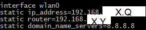
My typo on the third row disabled internet access to the RPI.
It should be routers.

Finally, I made a reservation for my RPI in my DLink router to ensure that no other device will get the same IP number.
With these changes, the RPI will always get the same IP on this network.

Step 5: Firewall and Antivirus
I'm following the Raspberry PI guide for security.

There is a discussion in the Linux community whether antivirus or firewalls are needed for Linux. Those who say that it isn't needed mean that there are very few viruses targeting Linux. To me, it sounds like "famous last words".

For my system, I personally don't see a great threa.t - I don't save any personal data on my mini computer. I will install it anyways for curiosity. I installed clam antivirus and the iptables/ufw firewall.

I created a new user with root privileges. When trying to ssh to the RPI, I was rejected. I had to add the user to the AllowUsers tag in /etc/ssh/sshd_config file.

Another measure to increase security of the RPI would be to change the SSH port number (default port is 22). Then, an attacker would need to scan the different ports for a SSH connection. Changing port number can be done by editing /etc/ssh/sshd_config.

Conclusion:


Now, the RPI is up and running with an acceptable security. I have a grip on the basics on the Arduino and I've been able to setup a project with a LCD display, several LED's, a potentiometer and a push button. 

The next step will be to connect a 8$ web camera to the Raspberry PI and to set up a web server on that micro computer.

Saturday 21 November 2020

IOT: Traffic Lights with Arduino - Timer

In the previous blog post, I created a pair of traffic lights. I also added a push button for emergency vehicles that activated a RGB LED that blinked (blue/red).

Now, I'll add a LCD display that will show how long the cars/bicycles need to wait for green light.

The LCD Display

The display that I'll use is a monocromatic display that can show two rows with 16 characters each. It has 16 pins and I'll use 12 of them:

  1. GND - Ground/Cathode. 
  2. VCC -  Anode. Connected to the 5V DC pin on the Arduino Uno board
  3. V0 - Controls the contrast of the display. The user controls the display by turning the knob of the potentiometer that is connected to V0.
  4. RS - Register Set. This pin decides whether to write data to the data register or to the instruction register. 
    1. The contents of the data register goes to the screen. 
    2. The instruction register contains instructions about what to write in the near future.
  5. RW - Select reading or writing mode. I connect it to ground, setting the LCD in permanent writing mode.
  6. E - Enable pin. This pin informs the LCD that it will receive data.
  7. D0 - not used in this case. The LCD can receive the data using either 8 data pins (quicker) or using 4 pins (simpler design). In my case, I'll go for simplicity instead of speed.
  8. D1 - not used.
  9. D2 - not used.
  10. D3 - not used.
  11. D4 - Data pin.
  12. D5 - Data pin.
  13. D6 - Data pin.
  14. D7 - Data pin.
  15. LED+ -  Connected to anode using a 220 ohm resistor.
  16. LED- - Connected to ground.

The Physical Connections

The traffic lights to the left will turn green in 14 seconds.

I had to re-wire the existing LEDs a bit to make the LCD fit to the breadboard. I also ran out of digital pins so I have used three analog pins to power the right set and one analog pin as an input from the push button. 

The Code

I added code for estimating the remaining time until the left and red set of traffic lights turns green. It takes the time in the current state into account and sums up the remaining states until the light turns green.

In case of emergency, the times will temporarily be set to 99 s.

The code is available here.

Next steps:

I'll bring up the Raspberry PI and connect it to the Arduino board. After that,  I want to send some small messages to the LCD on the arduino board.


Saturday 14 November 2020

IOT: Traffic Lights with Arduino

My first IOT project will be a pair of traffic lights that are simulating an intersection.

Iteration 1 - Time Controlled Traffic Lights: 

I've connected six LED's to the outputs of the Arduino Uno. A simple C++ program controls it. The program toggles between the two sets of traffic lights in a sequence that is common in Europe. 

Design and the code that I wrote. I used TinkerCad for making the drawing.

The code and the latest version of the sketch is available on my TinkerCad page.

Step 2 - Emergency Button

The next step is to add an "Emergency Button". Whenever someone presses that button, both sets of traffic lights switches to red and wait until the user presses the button again. Further, the RGB led will blink during that time.   


I only use two input pins for the RGB LED, since that will blink in red or blue only.
I control the brightness of that LED with Pulse Width Modulation.

When the user pushes the button (button state changes to HIGH), the system will either enter or leave the emergency state.

I had some issues with the board leaving the emergency state. The fault was mine - I messed up the output numbers and I sent output to input ports.

The next step will be more complex - I'll add a 16x2 LCD display to the system that will print some useful information to the user.

Saturday 7 November 2020

IOT: Getting Used with Arduino

 To learn Arduino, I've bought the Arduino Starter Kit. It contains an Arduino board, together with components needed for basic projects and a book that describes the projects. 

The first steps for me is to simply follow the examples in the book. I won't discuss this in detail in the blog, unless I do interesting findings.

Setting Up the Integrated Development Environment

Instead of downloading an Integrated Development Environment for Arduino, I decided to go for the web based option. The compilation of the code is done in the cloud (AWS). A small plugin (Arduino Create) is still needed on my laptop to handle the communication to the board.

Following the Book

From an engineering point of view, this isn't that interesting - but it was an important step. I needed to get my hands dirty and learn how to read the markings on the resistors, understand the difference between the long and short leg of diodes and understand why defensive programming is a good thing.


It is easy to make the first typo.
I did it, and I spent quite a while finding that bug.
If I had compared 7 to "a", the compiler would have complained immediately.

One of my favorite projects was the Crystal Ball, where a tilt sensor is connected to the board together with a Liquid Crystal Display. When the tilt sensor is activated, a random number is sent to the display.
The black box on the right side is the tilt sensor -
a little metallic ball that closes a pair of
connectors when the box tilts.
My Own Project 
Following a book isn't sufficient - I need to do something on my own. The next step is to create a pair of traffic lights with some extra functionality. I'll explore that in the next blog post.